Corrugated cardboard is one of the most widely used packaging products on the market today. Due to its superior usability and excellent processability, it has gradually replaced other packaging and transportation methods, becoming a staple in transportation, packaging, and warehousing.
The quality of corrugated cardboard depends on the strength of the finished cardboard, which in turn depends primarily on the process used in the corrugated cardboard printing and packaging equipment during production. Therefore, the ability to increase production capacity without compromising cardboard strength is the core competitiveness of this equipment.

Working Principle of Water-Based Ink Printing Equipment:
Water-based ink printing equipment uses water-based ink, which is transferred to the printing plate via components such as the ink reservoir, ink pump, and ink roller. During the printing process, paper is fed smoothly and accurately through the leading edge feed unit, ensuring that the desired image is printed on the paper in the correct position.
Problems in Using Water-Based Ink Printing Equipment:
1. When the printing unit is split or reassembled, or the leading edge position is lost, re-alignment is required, impacting work efficiency and paper repeatability (±1mm);
2. The finished paper can vary, and repeated adjustments to the printing phase waste customers' cardboard costs and time;
3. Traditional printing presses are complex to operate. Determining the print point, including error offset phase, and adjusting the pressure for different box sizes, requires extensive experience, resulting in high labor and material costs.
1. Complex algorithms for one-touch plate registration, local zero return, local wipe, local hang, local print point search upon closing, and automatic wipe location search by the extension unit;
2. Determining the print point, wipe, and hang position is complex, requiring calculations based on different printing positions and substrates;
3. Perfect coordination is required between the die-cutting and paper-feeding units, requiring precise adjustment of pressure and printing phase based on the die-cutting unit's box shape and paperboard specifications.
The die-cutting, crimping, and slotting unit consists of three components: the die-cutting roller and backing roller (hereinafter referred to as the die-cutting unit), the upper and lower crimping rollers and the die-cutting blade alignment unit (hereinafter referred to as the die-cutting unit), and the die-cutting blade and crimping roller pressure adjustment unit (hereinafter referred to as the pressure adjustment unit). Before slotting, the die-cutting unit arranges the blades, adjusts the pressure, and finally, after the die-cutting unit aligns with the leading edge using encoder signals, slotting begins, ensuring the paper slots are accurately positioned and cut to the correct depth.
Problems in Die-cutting, creasing, and slotting unit equipment:
1. The die-cutting unit pressure group formula is incomplete, and the formula setting is not flexible enough;
2. The power-off position of the die-cutting unit pressure group is missing, and the pressure group pressure adjustment is inaccurate due to the eccentric wheel structure;
3. The die-cutting unit slotting phase is inaccurate, with the paper slotting deviation exceeding ±0.5mm;
4. Phase adjustment is difficult, the phase adjustment reference is confused, and repeated phase adjustment wastes material and time costs;
5. The free die-cutting unit cannot achieve infinite slotting when the paper is too long.
1. How to edit the die-cutting recipe function screen to quickly debug the die-cutting while ensuring freedom of movement;
2. How to set the phase adjustment reference for simple and convenient phase adjustment;
3. How to perform real-time compensation during die-cutting operation to ensure slotting accuracy within ±0.5mm;
4. How to integrate unlimited slotting functionality into an independent die-cutting unit

Advantages of Ink Printing Solution
1. Simple and Convenient Operation
SINEE solution eliminates the need for repeated zeroing and plate alignment when closing and closing the machine, automatically finding the printing position, plate wiping position, and plate hanging position. It supports one-touch plate registration, plate hanging, plate wiping, and closing and closing the machine. It supports MES system data access and barcode scanner data access. The simple and clear interface addresses issues such as operator inexperience and operational difficulties.
2. Simple Phase Adjustment
SINEE solution allows for convenient phase adjustment even when printing position errors occur, ensuring printing accuracy of ±1mm. It supports one-touch order placement for different box sizes in the die-cutting group, automatically adjusting voltage and printing phase to ensure accurate printing position, saving customers the cost and time of test paper testing

Advantages of the Die-Cut, Crimping, and Slotting System Solution
1. Comprehensive Configuration:
SINEE solution supports 13 box types, including one-page boxes, one-page full-cover boxes, two-page boxes, one-page bottomless boxes, two-page bottomless boxes, and top and bottom lid boxes. It supports both standard slotting and unlimited slotting. It supports standard tooling, code scanning tooling, and tooling connected to an MES system. It supports individual compensation and modification of length, width, and height coefficients, meeting customers' needs for large, small, and bulk orders.
2. Simple Phase Adjustment:
SINEE solution utilizes phase calibration, automatically aligning the phase before paper feeding. When phase adjustment is accurate, a 100mm phase setting corresponds to a 100mm distance from the paper tip to the slot, and a 400mm box height setting corresponds to a 400mm width between the two slots. This simple and intuitive process eliminates the need for back-and-forth adjustments. When switching between box types for the same fluting configuration, the phase and box height error is less than ±0.75mm, saving customers the material and time costs of testing paper.
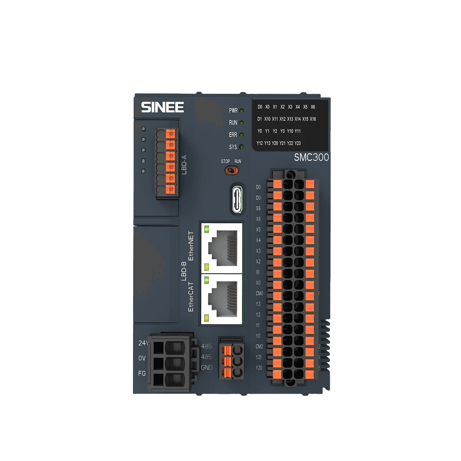
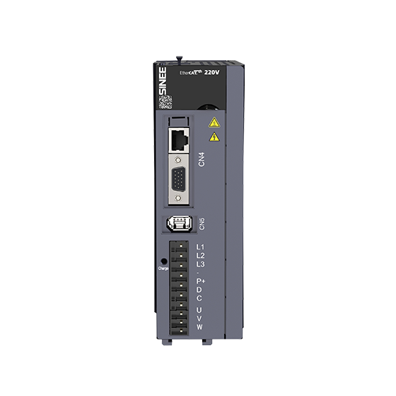
3. EtherCAT Bus Drive + 23-bit Absolute Multi-turn Encoder:
SINEE driver utilizes an EtherCAT bus solution, offering convenient on-site wiring and strong anti-interference capabilities. Proximity pulse systems are complex to wire and can suffer from pulse loss during operation. The motor uses a 23-bit absolute multi-turn encoder, ensuring position retention without power failure and eliminating the need for repeated mechanical origin calibration.
4. Real-time Die-cutting Spindle Compensation:
SINEE solution achieves die-cutting accuracy within ±0.75 by real-time calibration of the external spindle encoder input position with the servo die-cutting spindle position.


 Address : Room 804, 8F, Building 1, Runzhi R&D Center, No. 5 Runfang Road, Block 70, Xingdong Community, Xin'an Sub-district, Bao'an District, Shenzhen
 Tel : 027-87002560
 Fax : 86-0755-86267216
 Email : info@sineedrive.com
Cpyright © 2023 Shenzhen Sinee Electric Co.,Ltd. A certain ICP preparation No. 00000000-0